Rupert Neve Designs from the 60s and 70s Realistically Recreated by the Yamaha K’s Lab Research Team
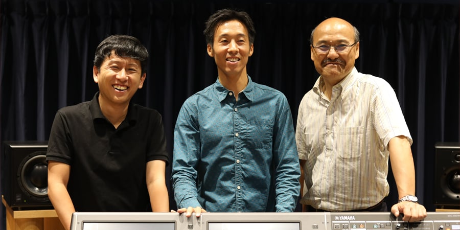
K’s Lab members (left to right) Yoshitaka Uratani, Hajime Komura, and Toshifumi Kunimoto.
K’s Lab has been a central research group at Yamaha for 30 years, garnering international attention for breakthroughs in physical modeling while leaving an impressive track record in product development. The K’s Lab team put their full technological weight behind the recreation of professional audio gear such as equalizers and compressors originally developed by Rupert Neve in the 60s and 70s. Readers might wonder why Yamaha chose to research products from another manufacturer. The answer lies in the undeniable fact that in many ways Mr. Neve built the foundations of the pro audio industry as we now know it, and it is with the greatest respect that the team now works with Mr. Neve to build the future.
In the first installment of this three-part series, “How the discovery of a 1977 thesis led to a breakthrough at the Yamaha K’s Lab research division 30 years ago,” we introduced K’s Lab and learned a little about their history. In this, the second installment, we’ll look at what it takes to recreate equalizers and compressors from the 60s and 70s using physical modeling technology, as described by members of the K’s Lab research team.
As mentioned in the previous installment, the K’s Lab research group is located at Yamaha headquarters in Hamamatsu, Japan, led by research fellow Dr. Toshifumi Kunimoto. People with interests in music and research gather here from universities all around the country to take part in research covering a variety of topics. Although the team’s focus was initially “virtual acoustic synthesis,” the simulation of acoustic sound using physical modeling technology, that was later expanded to include precise physical modeling of electronic circuitry. VCM (Virtual Circuitry Modeling) that can accurately recreate vintage effects and signal processors has become a main theme at K’s Lab.
Dr. Kunimoto remembers that “Meeting Mr. Neve, a legend in the industry, was a vital key to our progress. He is a brilliant engineer who has created a large number of historically important devices. We had actually been examining and modeling vintage equipment designed by Mr. Neve even before we had the honor of meeting him in person, and had developed a deep understanding of many of their key characteristics. Thanks to that background, mutual understanding was quickly established, and that paved the way for the research we are currently engaged in with invaluable cooperation from the RND (Rupert Neve Designs) company.”
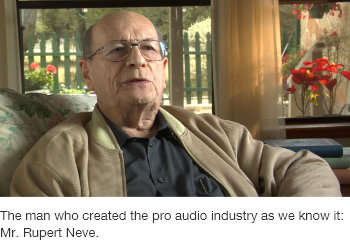
Mr. Rupert Neve was born in England, and at the time writing is 92 years old. In the course of his illustrious career he was involved in the establishment of Neve, Focusrite, and Amek, all well-known companies that produced some now legendary audio equipment. Many readers will immediately associate the 2254 comp/limiter, 33609 comp/limiter, and 1073 microphone preamplifier/EQ with the Mr. Neve name.
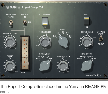
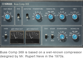
In the following discussion we’ll take a closer look at the Rupert Comp 754 and Buss Comp 369. These are both immaculate digital recreations of devices designed by Rupert Neve in the 60s and 70s, many of which are still in use in studios around the world. The Rupert Comp 754 and Buss Comp 369 models created by K’s Lab are currently included in Yamaha’s acclaimed RIVAGE PM series Digital Mixing System.
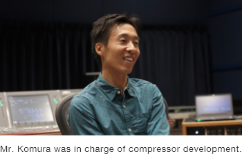
Mr. Hajime Komura, an assistant manager at K’s Lab, explains: “Compressors generally fall into one of two categories: those that use feed-forward control and those that use feedback control. Most of today’s compressors are feed-forward types in which the level of the input audio signal is detected and used to control compression. Feed-forward compressors produce a ‘contemporary’ sound with smooth output. In vintage comps that are still in demand like the 1176, LA2A, and 33609, on the other hand, the output signal level is detected and fed back to control compression. Feedback compression has a thicker, richer sound.” Mr. Komura showed us a block diagram (reprinted below) that the team referred to when creating the Rupert Comp 754 and Buss Comp 369.
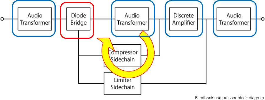
Mr. Komura continues: “Compressor/limiters designed by Mr. Neve in the 60s and 70s have three main characteristics. The first is that they are all feedback types. The second is that they all use diode bridge compression circuits. And the third is that they all use transformers and discrete amplifier circuitry for input and output. This schematic diagram shows a diode bridge compression circuit.”
This gets a bit technical, but the section of the diagram enclosed in the blue square below is the “diode bridge.” It includes four diodes to which a control voltage fed back from the output is applied. Diodes are best known for their ability to pass a signal in one direction only, plus to minus, but here they function as variable resistors that produce compression.

Mr. Komura adds: “Diode bridge compression circuits are rare these days, but when the circuit is accurately simulated we find that the non-linear diode response curve results in natural sounding compression. That’s why it doesn’t have an artificial ‘compressor’ type sound.”
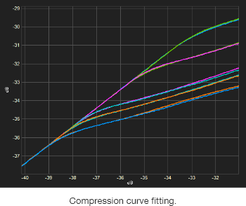
These colored gain reduction frequency plots represent frequency response variations at different input levels, and they are very interesting. There is a dip at the low frequency end, followed by a broader scoop in the mid frequency range, and then a slight rise at the high frequency end. The same overall frequency response is maintained at all levels, so the sound doesn’t lose presence or recede when compression is applied. We can assume that was Mr. Neve’s intent when he designed these circuits in the 60s and 70s.
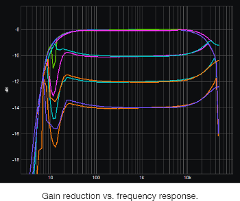
Another characteristic of these devices that makes an important contribution to their sound is that they employ transformers and discrete amplifier circuitry at the input and output stages.
According to Mr. Komura, “The transformers in particular are essential to the Rupert Neve sound. This is because of their frequency response and magnetic saturation distortion, neither of which can be created with amplifier circuitry alone. We have accurately recreated the transformer sound by modeling even the subtle distortion artifacts. The balance between the odd and even harmonic distortion of discrete class-A amplifier circuits is also vital to the sound, so that has also been meticulously modeled to recreate the necessary complex harmonic structure.”
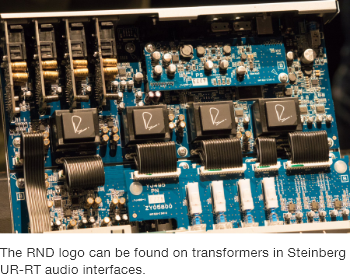
The fact that Steinberg UR-RT2 and UR-RT4 audio interfaces include RND transformers has recently sparked a lot of interest. K’s Lab has also simulated these and other transformer circuits in detail.
Mr. Komura points out that “We try to recreate each device as closely as possible, step by step, with detailed VCM simulations. We can’t model every individual resistor and capacitor, so we might model the physical response of a diode bridge, for example, and combine that with other modules to recreate a compete circuit. Increased DSP power has made it possible to do the necessary processing in real time.”
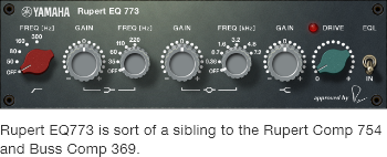
Rupert EQ 773 is a VCM recreation of a musical-sounding equalizer from the 70s that was sort of a “sibling” device to the compressors modelled in the Rupert Comp 754 and Buss Comp 369. Mr. Yoshitaka Uratani was the assistant manager in charge of developing the Rupert EQ 773.
Mr. Uratani: “The equalizers developed by Mr. Neve in the 60s and 70s were extremely musical, and are still in demand today. They are often traded at high prices. I wanted to recreate their sound, so with cooperation from Dr. Kunimoto and Mr. Komura, original design specification supplied by Mr. Neve, and a series of very deep discussions, the Rupert EQ 773 was born. Component-level modeling played an important role in this case.”
The VCM modeling process begins with a reference device that is carefully analyzed, both in terms of electrical performance and analog circuit configuration. When the mid-peaking response of one of these equalizers is measured, we see a very distinctive characteristic in the high-frequency range.
Mr. Uratani: “When sound engineers evaluated the actual device by ear, they also commented that the distinctive high-end response was a notable feature of the mid-peaking sound. That characteristic was clearly a key feature, so we spared no effort in modeling it accurately.”
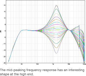
That unusual shape is clearly visible in the measured frequency response. There is an interesting fan-shaped area in the high-frequency range that has a large effect on the overall sound. In order to replicate that response Mr. Uratani began analyzing the circuit at the component level. His analysis led to the discovery that a third order transfer function would have to be used, rather than the second order transfer function normally used for EQ. An earlier comment by Dr. Kunimoto comes to mind: “Component-level emulation is the essence of VCM technology.”
Mr. Uratani: “At the time, the coils that were often used to produce a mid-peaking response were far from perfect. Mr. Neve understood that, and designed the circuitry to achieve the best possible overall balance.”
The equalizer’s low-shelving response was modeled through a similar process of analyzing the reference device followed by repeated modeling and testing.
Mr. Uratani: “It is interesting to note that the same type of circuit can be used for both high and low shelving, but when simulated that way the resultant response graph is just normal. That is not the result we get when we measure the actual device. After much searching we found that the reason lies in the simplified circuit mentioned earlier. Reading Mr. Neve’s documentation carefully we realized that, unlike basic op-amp amplifiers, his amplifiers were designed to achieve an optimum balance between sound and the limitations of the components available at the time.”
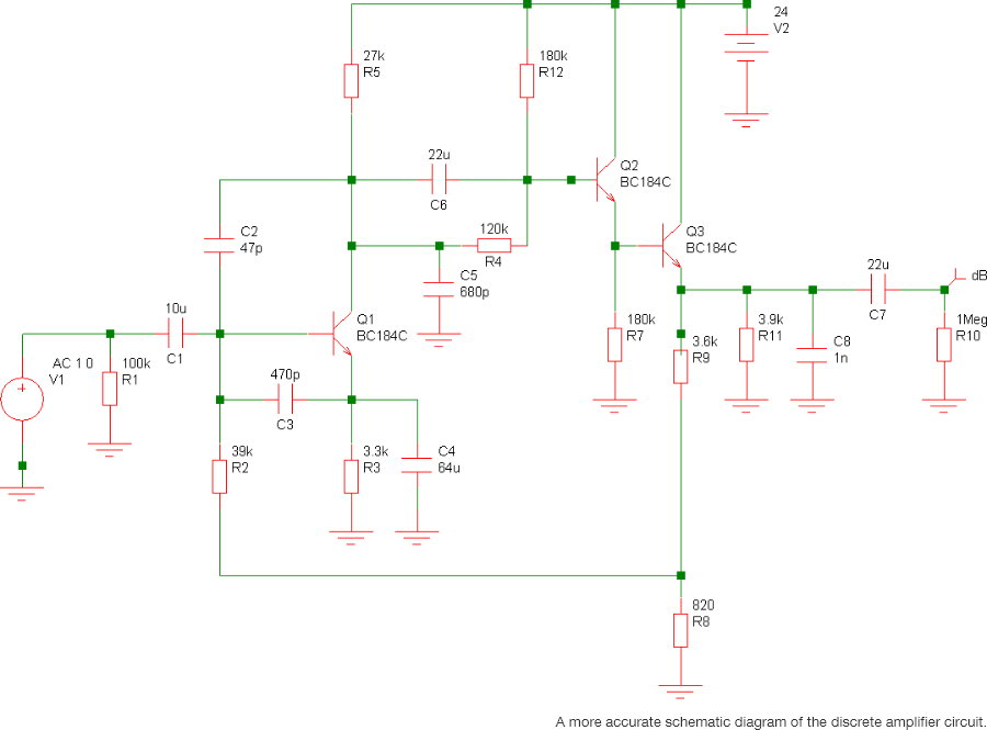
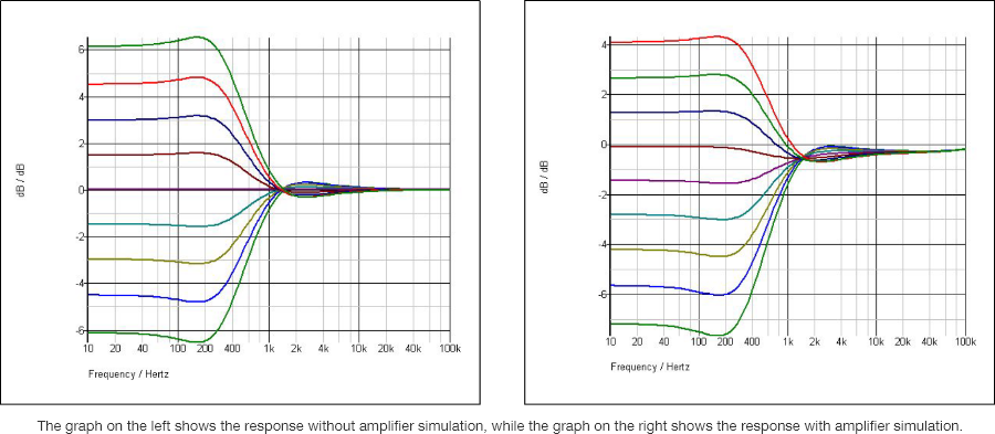
One important point is the use of an AC feedback circuit. While a fixed voltage is applied in standard amplifier circuits, AC feedback that will naturally modulate the signal is used in this case. In order to simulate that situation, VCM technology was used to analyze the discrete circuit at the component level and simulate individual transistors. The measured results almost exactly match the original device, as does the model’s audible response when the gain knob is adjusted.
As we have seen, K’s Lab recreates the sound and performance of vintage equipment through diligent research and repeated experimentation. One question that arises is, what are the backgrounds of the people who work there? Although there is a great deal of variety, two of the engineers introduced in this article have something in common. Mr. Komura and Mr. Uratani both came to K’s Lab as interns during their university or graduate school years.
Mr. Komura explains: “In university I was doing research related to semiconductor lithography. Sound and signal processing were totally outside my field. But I loved music, and when I learned that Yamaha had an internship program I came to see if I could participate. The experience of writing software simulations that had a huge effect on sound were extremely interesting to me.”
The fact that this top-class research facility has an intern program is interesting too.


