Better Sound for Commercial Installations
Part 3: Mixers and Processors

06. Feedback Control - Using an Equalizer
Feedback occurs at a specific frequency that is emphasized more than others. It stands to reason that if you can locate that frequency and reduce it's level, you can stop the feedback. Equalizers are ideal for this purpose, so in this section we'll look at how graphic equalizers are used for feedback control.
Graphic Equalizer Frequency Bands

As we learned in the "Processing Types" section, graphic equalizers divide the audio spectrum into a number of frequency bands that can be individually adjusted as required. A graphic equalizer may have 7, 15, or 31 bands, or some other configuration. The number of bands is often included when referring to a specific type of graphic equalizer: "15-band graphic equalizer," for example. The more bands a graphic equalizer has, the finer the control it can provide.
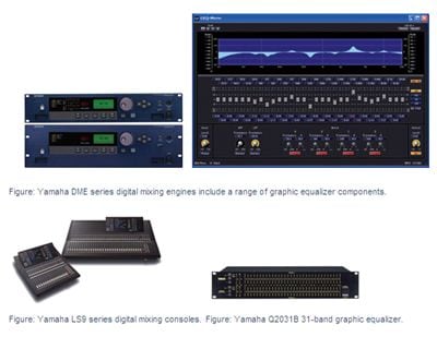
Yamaha DME series digital mixing engines include 7-band, 15-band, and 31-band graphic equalizer components. Yamaha digital mixing consoles such as LS9 series feature 31-band graphic equalization. Yamaha also offers the stand-alone analog Q2031B 31-band graphic equalizer.
Using a Graphic Equalizer for Feedback Control

The frequency at which feedback is occurring is often referred to as the "feedback point." Experienced operators can usually determine the feedback point by ear, or at least come very close. The less experienced among us have to use a more procedural approach, as follows.
With the speaker systems and microphones positioned as they will be during actual use, the process begins with the volume turned down and all of the equalizer's controls set to their "0" (flat) positions. The volume is then gradually increased until feedback occurs. The pitch of the feedback tone provides a clue as to where to start making tentative adjustments. If the feedback pitch is high, the offending frequency is likely to be in the upper range, whereas if the feedback pitch is low adjustments will need to be made in the low frequency range.
(Figure: The first step in locating the feedback frequency.)

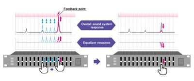
Next, the volume is lowered to the point at which the feedback stops. The individual equalizer controls within the likely feedback range are then raised (boosted) and returned to zero one by one until the feedback tone heard in the first step above reoccurs. When that happens the feedback point has been located, and lowering that control to about 3dB or 6dB below its zero setting will probably prevent the same feedback from occurring when the overall volume is raised back to the working level. Sometimes there is more than one feedback point, and the process may have to be repeated a number of times to effectively eliminate all feedback.
(Figure Left: Boost the bands one by one to locate the feedback point.
Figure Right: Attenuate the band that corresponds to the feedback point by 3 to 6dB)
Although a graphic equalizer that allows easy visual confirmation of the adjustments made was used for the procedure described above, the procedure for using a parametric equalizer for feedback control is similar.
The process of using an equalizer for feedback control is relatively easy to describe, but a variety of problems can occur in actual practice. We'll cover some of the difficulties in the next section. Of course there's an effective way to circumvent those problems, and we'll introduce that as well.
Contents
The sound systems that broadcast the information you're hearing have been carefully designed and installed to suit the needs of each individual facility.
This series offers information aimed at achieving the best possible sound in commercial installations, from the basics to equipment selection and day-to-day operation.


